Introduction to ESP32 — Getting Started
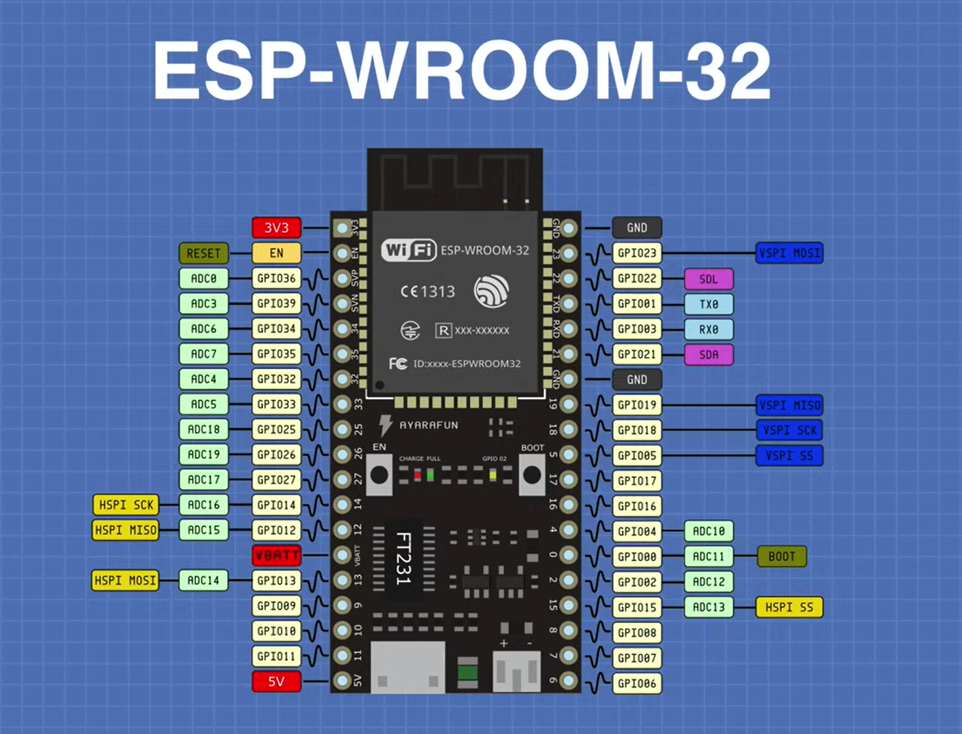
I recently bought an ESP32 and spent a good amount of time just getting it to work before writing a single line of code. So I figured I'd document the whole process here so someone else doesn't waste the same time.
What even is the ESP32?
It's a microcontroller with WiFi and Bluetooth built in. You write code, flash it to the board, and it runs that code forever. Simple as that. What makes it worth buying over an Arduino is the wireless support and the fact that it runs at 240MHz for around ₹380.
Setting up Arduino IDE
Download Arduino IDE 2.x from arduino.cc. Then go to File, Preferences, and paste the Espressif boards URL
https://raw.githubusercontent.com/espressif/...
into the Additional Boards Manager field. After that go to Boards Manager, search esp32, and install the package by Espressif Systems. Once done select ESP32 Dev Module as your board.
The driver situation
First time I plugged in my ESP32, Windows didn't detect it at all. Turns out you need the CP2102 driver from Silicon Labs.
Download it, go into the x64 folder, right click the silabser Setup Information file and hit Install. Replug the board and it should show up under Ports in Device Manager.
Also if nothing shows up even after the driver, check your cable. Charge only cables won't work here. You need a proper data cable.
Blinking the LED
GPIO 2 is the onboard LED on this board. The standard Arduino blink example won't work directly because LED_BUILTIN isn't defined for ESP32. Just replace it with the number 2 and it works fine.
If uploading gets stuck at "Connecting.....", hold the BOOT button on the board while it connects, then let go. Common thing with ESP32.
Connecting sensors
After getting the blink working I connected a DHT11 on GPIO 4 for temperature and humidity readings. Then wired a 0.96 inch OLED display using I2C on GPIO 21 and GPIO 22. Got live sensor data showing on the screen without needing a PC. That's when it actually starts feeling like something real.
If your OLED is detected but shows nothing, swap your SDA and SCL wires. Fixed it for me instantly.
Code
All the code from this post is on GitHub at www.github.com/omn7/ESP32S-NodeMCU-controls
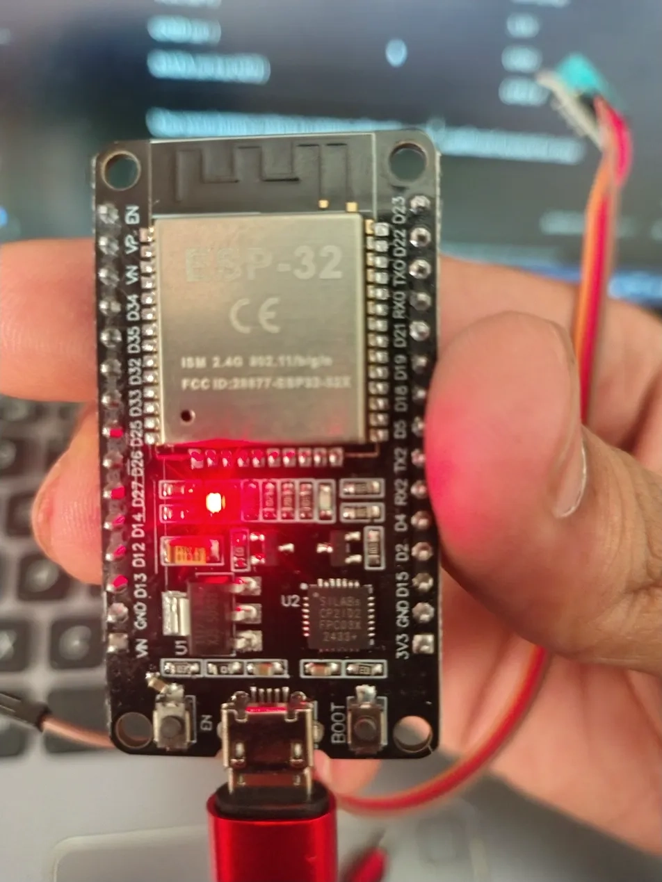
If you have just picked up an ESP32 DevKit, this guide walks through the board — every pin, every component, and what you can actually do with them.
The Main Module: ESP32-WROOM-32
That silver metallic block is the brain of the board. It includes:
- Dual-core Xtensa LX6 CPU: running at 240MHz
- 520KB SRAM: + 4MB Flash storage
- Wi-Fi: — 802.11 b/g/n, 2.4GHz (the "ISM 2.4G" label on the module)
- Bluetooth 4.2 + BLE
- Built-in PCB antenna (the trace pattern at the top edge)
- FCC certified (FCC ID printed on the module)
Other Components on the Board
| Component | What It Is | Role |
|---|---|---|
| SiLabs CP2102 | USB-to-UART bridge | Converts USB signals to serial so you can flash code from your PC |
| AMS1117 | 3.3V voltage regulator | Steps down 5V (from USB) to 3.3V for the ESP32 |
| Red LED | Power indicator | Lights up when the board has power |
| EN button (left) | Reset button | Restarts the ESP32 — does not erase code |
| BOOT button (right) | Flash mode button | Hold while pressing EN to enter firmware upload mode |
| USB-C port | Power + data | Powers the board and uploads code via CP2102 |
| SMD capacitors/resistors | Passive components | Power filtering and stabilization |
Left Side Pins (Top → Bottom)
| Pin Label | Type | Details |
|---|---|---|
| EN | Control | Chip Enable. Pull LOW to reset. Tied to EN button on board |
| VP | Input only | No internal pull-up/down. Analog input ADC1 channel 0 |
| VN | Input only | No internal pull-up/down. Analog input ADC1 channel 3 |
| D34 | Input only | Analog ADC1 channel 6. Cannot be used as output |
| D35 | Input only | Analog ADC1 channel 7. Cannot be used as output |
| D32 | Input/Output | Analog ADC1 ch4, Capacitive Touch, RTC capable |
| D33 | Input/Output | Analog ADC1 ch5, Capacitive Touch, RTC capable |
| D25 | Input/Output | Analog ADC2 ch8, DAC1 — true analog voltage output |
| D26 | Input/Output | Analog ADC2 ch9, DAC2 — true analog voltage output |
| D27 | Input/Output | Analog ADC2 ch7, Capacitive Touch, RTC capable |
| D14 | Input/Output | Analog ADC2 ch6, Capacitive Touch, HSPI CLK — boot-sensitive |
| D12 | Input/Output | Analog ADC2 ch5, Capacitive Touch, HSPI MISO — boot-sensitive, avoid pulling HIGH at boot |
| GND | Power | Ground |
| D13 | Input/Output | Analog ADC2 ch4, Capacitive Touch, HSPI MOSI |
| VIN | Power | 5V input — use this to power the board externally without USB |
Right Side Pins (Top → Bottom)
| Pin Label | Type | Details |
|---|---|---|
| D23 | Input/Output | VSPI MOSI — SPI data output line |
| D22 | Input/Output | I2C SCL — clock line for I2C devices like OLED, sensors |
| TXO | Output | UART0 TX — USB serial transmit. Avoid using as GPIO while uploading code |
| RX0 | Input | UART0 RX — USB serial receive. Avoid using as GPIO while uploading code |
| D21 | Input/Output | I2C SDA — data line for I2C devices |
| D19 | Input/Output | VSPI MISO — SPI data input line |
| D18 | Input/Output | VSPI CLK — SPI clock line |
| D5 | Input/Output | VSPI CS — SPI chip select. Boot-sensitive, outputs PWM signal at boot |
| TX2 | Input/Output | UART2 TX — second hardware serial port transmit |
| RX2 | Input/Output | UART2 RX — second hardware serial port receive |
| D4 | Input/Output | Analog ADC2 ch0, Capacitive Touch, RTC capable |
| D2 | Input/Output | Analog ADC2 ch2, Capacitive Touch — boot-sensitive, onboard LED on some boards |
| GND | Power | Ground |
| D15 | Input/Output | Analog ADC2 ch3, Capacitive Touch, HSPI CS — boot-sensitive |
| 3V3 | Power | 3.3V output from onboard regulator — power 3.3V sensors from here |
Power Pins Summary
| Pin | Voltage | Use |
|---|---|---|
| VIN | 5V | External power input (bypasses USB) |
| 3V3 | 3.3V | Power output for sensors (max ~600mA) |
| GND | 0V | Common ground — multiple GND pins on both sides |
Boot-Sensitive Pins — Important!
These pins affect how the ESP32 starts up.
Avoid connecting anything that pulls them HIGH or LOW at power-on.
| Pin | Boot Behavior |
|---|---|
| D2 | Must be LOW or floating at boot |
| D5 | Must be HIGH at boot |
| D12 | Must be LOW at boot — affects flash voltage |
| D14 | Can cause issues if driven at boot |
| D15 | Must be HIGH at boot |
Communication Protocols
| Protocol | Pins |
|---|---|
| I2C | SDA = D21, SCL = D22 |
| SPI (VSPI) | MOSI = D23, MISO = D19, CLK = D18, CS = D5 |
| SPI (HSPI) | MOSI = D13, MISO = D12, CLK = D14, CS = D15 |
| UART0 | TX = TXO, RX = RX0 (used by USB serial) |
| UART2 | TX = TX2, RX = RX2 |
Quick Mental Model
- Left side: — analog-heavy. VP, VN, D34, D35 are input-only. D25 and D26 have true analog output (DAC).
- Right side: — digital communication. I2C, SPI, and two UART ports all live here.
- Bottom: — EN (reset), USB-C (power + flash), BOOT (flash mode trigger).
- Top: — ESP32-WROOM-32 module with Wi-Fi + Bluetooth + antenna.
- *The ESP32 is one of the most capable microcontrollers for the price.
With built-in Wi-Fi, Bluetooth, dual cores, and 30+ GPIO pins, it is
a go-to choice for IoT, home automation, robotics, and wireless projects.*